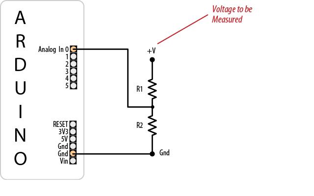
After I plan to have a new project with Arduino, I need to know how to build a circuit that can read voltage or what we can call it voltage reader using Arduino.
I found this site and have tried it. But, it seems like the program has a lot of error. I tried it with 1.5V AA battery and it gave me 350V??!!!

const int referenceVolts = 5; // the default reference on a 5-volt board
//const float referenceVolts = 3.3; // use this for a 3.3-volt board
const int R1 = 3000; // value for a maximum voltage of 20 volts
const int R2 = 1000;
// determine by voltage divider resistors, see text
const int resistorFactor = 255 / (R2/(R1 + R2));
const int batteryPin = 0; // +V from battery is connected to analog pin 0
void setup()
{
Serial.begin(9600);
}
void loop()
{
int val = analogRead(batteryPin); // read the value from the sensor
float volts = (val / resistorFactor) * referenceVolts ; // calculate the ratio
Serial.println(volts); // print the value in volts
}
First of all we need to understand capability of Arduino to read analog signal/voltage. Arduino can accept not more than 5V in its analog input. But it reads digitally in interger (we set the variable as A) between 0 to 1024. That’s mean between 0V to 5V. So, between interger 0 to 1 is Vref/1024, where Vref is voltage reference. Voltage reference is depending on Arduino board. Some boards using 5V (mostly used) and some is using 3.3V.
Voltage read by arduino, Vo = (A * Vref)/1024
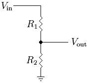
Next the circuit. The circuit for analog is used to make sure the voltage we measure to arduino not exceed 5V. But, we need arduino measure voltage maximum 20V just for example. So, voltage divider circuit can help us to limit the voltage to arduino and at the same time to get accurate voltage measurement from the source.

In voltage divider, it has voltage ratio.
Voltage ratio = Vo/Vi = R2 (R1+R2)
Vo = (Vi * R2)/(R1 +R2)
For my case, R1 is not 3k Ohm and R2 is not 1k Ohm. In reality or maybe I got faulty resistors, my R1 is 2980 Ohm and R2 is 980 Ohm. So, in the new program, I am not using R1 and R2 according to their label but measure them first using multimeter.
From both equation, we can merge them together to
(Vi * R2)/(R1 +R2) = (A * Vref)/1024
Vi = ((A * Vref)*(R1 + R2))/(1024 *R2), where Vi will be voltage we measure.
This formula can be used in arduino programming to get nearly accurate reading. The reading is not involve any internal resistor exist in battery.
Then we look at the early programming. The constants type for R1 and R2 should be float not integer. Integer value can not give a float value after we calculate the voltage ratio. It will return 0.
Then, we can strikeout some equations in the program. We can straight away using final equation we got above.
Below is the programming I write like the theory above.
const int referenceVolts = 5; // the default reference on a 5-volt board
//const float referenceVolts = 3.3; // use this for a 3.3-volt board
const float R1 = 3290; // value for a maximum voltage of 20 volts
const float R2 = 980;
// determine by voltage divider resistors, see text
const int batteryPin = 0; // +V from battery is connected to analog pin 0
void setup()
{
Serial.begin(9600);
}
void loop()
{
float volts = ((analogRead(batteryPin)*referenceVolts)*(R1+R2))/(1024*R2) ; // calculate the ratio
Serial.println(volts); // print the value in volts
}
