
If you’ve ever dabbled in small-scale solar — whether it’s powering a remote sensor node, a farm monitoring station, or just a shed light that you’re tired of replacing batteries for — chances are the Renogy Wanderer has crossed your radar. It’s affordable, compact, and widely available. But as with most budget gear, there’s a gap between what the spec sheet says and what you actually experience in the wild. This post fills that gap — with real-world notes, hardware war stories, and enough Modbus register maps to make your inner maker very happy.
What Is the Renogy Wanderer?
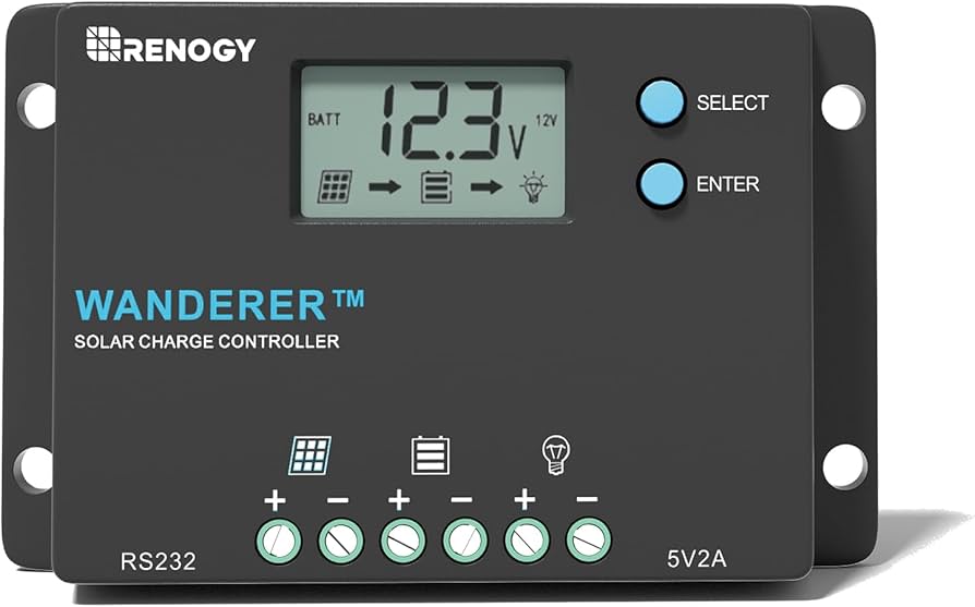
The Renogy Wanderer is a PWM (Pulse Width Modulation) solar charge controller available in 10A and 30A variants. It sits in the budget-friendly segment of Renogy’s lineup, designed for small off-grid systems — think RVs, boats, cabins, garden sheds, and remote IoT deployments.
Key specs at a glance:
- Rated charge current: 10A or 30A
- Nominal voltage: 12V/24V auto-recognition (non-lithium) or manual set
- Max PV input voltage: 25V (30A) / 50V (10A)
- Max PV input power: 400W (12V system)
- Charging stages: 4-stage PWM — Bulk, Boost, Float, Equalization
- Display: Backlit LCD (10A) / LED indicators (30A)
- Connectivity: RS232 port (compatible with BT-1 Bluetooth module)
- Protections: Overcharge, over-discharge, short circuit, overload, reverse polarity, reverse current, temperature compensation
- Operating temperature: -20°F to 113°F (-29°C to 45°C)
For the price, it punches well above its weight — especially if you don’t need MPPT efficiency and just want something that reliably keeps your battery topped up.
The LiFePO4 Problem — And the Workaround
Here’s where things get interesting — and slightly frustrating if you’re running a LiFePO4 battery like most modern makers do.
The standard Wanderer’s battery type menu offers three options: SEL (Sealed/AGM), GEL, and FLU (Flooded). Notably absent: a dedicated LiFePO4 profile. The “Wanderer Li” variant adds lithium support, but the standard model? No such luck.
After testing, the GEL profile is the safest workaround for LiFePO4. Here’s why:
- GEL float voltage: ~13.8V — within safe range for LiFePO4
- GEL equalization: N/A / disabled — LiFePO4 doesn’t need equalization anyway
- GEL boost voltage: stays within acceptable limits
The FLU (Flooded) profile is a hard no. It pushes equalization voltage well above 14.4V — and LiFePO4 cells have a strict upper threshold right around there. Go over it, and the battery’s BMS trips. The Wanderer detects the sudden disconnection and throws error code E04 on the display, shutting down the output terminal. Your load dies, and you’re left staring at a blinking error code wondering what went wrong.
Summary: GEL = safe LiFePO4 workaround. FLU = E04 error and a bad time.
What the Display Tells You (And What It Doesn’t)
The Wanderer 10A’s LCD cycles through system parameters — handy for a quick sanity check. But if you’re expecting a full picture of your power flow, you’ll be disappointed.
What you DO get:
- ✅ PV (solar panel) voltage
- ✅ Battery voltage
- ✅ Charging state indicator
- ✅ Error codes
What you DON’T get:
- ❌ Output (load) voltage at the load terminals
- ❌ Output current draw
- ❌ Output wattage
That’s a significant blind spot if you’re monitoring what your load actually consumes. You can’t tell from the display how much current your connected devices are pulling from the load terminals. For any serious energy monitoring — especially in IoT or precision agriculture deployments — you’ll need to pull data via Modbus. Which brings us to the fun part.
RS232 Direct Connection: The “Nearly Melted” Experiment
The Wanderer has an RS232 port on the side — a small 3.5mm jack that carries Modbus RTU serial communication. Connecting an ESP32 to this via an RS232 TTL converter sounds straightforward on paper. In practice, it was a mini disaster.
Here’s what happened:
- Connected ESP32 → RS232 TTL converter module → Wanderer RS232 port
- Powered up the Wanderer (which supplies voltage through the RS232 jack to drive accessories like the BT-1)
- The RS232 converter module got extremely hot — borderline meltdown territory
- The ESP32 had trouble booting reliably whenever the Wanderer was producing output
The likely culprit: back-powering. The Wanderer’s RS232 jack provides power specifically intended to drive the BT-1 module. When a generic RS232 converter is plugged in instead, that power rail feeds back through the converter in ways it was never designed to handle — causing excessive heat and voltage conflicts on the ESP32’s power lines.
The converter was not happy. The ESP32 was confused. I was concerned.
Takeaway: The RS232 jack is designed for the BT-1, not general-purpose converters. If you want reliable communication, use the BT-1 and go wireless. Which leads us to the part that actually works.
BLE via Renogy BT-1: What Actually Works
After the RS232 adventure, I switched to the Renogy BT-1 Bluetooth module — a small dongle that plugs into the RS232 port and exposes Modbus data over BLE. This is the officially supported wireless path, and it works — but only once you understand how it actually behaves. Most online examples get it wrong.
The BT-1 BLE Map (Confirmed via nRF Connect)
This is the single most important thing to understand. Every example online assumes TX and RX share the same BLE service. They don’t.
| Direction | Service UUID | Characteristic UUID | Properties |
|---|---|---|---|
| Send Modbus request | FFD0 | FFD1 | Write |
| Receive Modbus response | FFF0 | FFF1 | Notify |
You write to FFD1 (under service FFD0), but you subscribe for notifications on FFF1 under a completely separate service FFF0. Miss this split, and you’ll spend hours wondering why your ESP32 sends data but gets nothing back.
Other Gotchas Worth Knowing
- Device name is empty during advertising. The BT-1 advertises with no device name. Don’t scan by name — match by service UUID
FFD0in your scan callback instead. - Modbus address is 255 (0xFF). The Renogy Wanderer uses address 0xFF, not the typical address 1. This is undocumented and only confirmed via community testing.
- Only one BLE connection at a time. If the Renogy DC Home app is open on your phone, the ESP32 cannot connect. Force-close the app first.
- Power cycle BT-1 if it stops advertising. After a dropped connection, the BT-1 sometimes stops advertising entirely until you physically unplug and replug it from the controller.
Modbus Register Map (Confirmed Working)
Based on community-verified data (credit to wrybread’s RS232 sketch as a reference baseline), here are the confirmed working registers:
| Register | Value / Scaling |
|---|---|
0x0100 | Battery SOC % |
0x0101 | Battery voltage × 0.1 V |
0x0102 | Charge current × 0.1 A |
0x0103 | High byte = controller temp °C, Low byte = battery temp °C |
0x0104 | Load voltage × 0.1 V |
0x0105 | Load current × 0.01 A |
0x0106 | Load watts |
0x0107 | Solar panel voltage × 0.1 V |
0x0108 | Solar panel current × 0.01 A |
0x0109 | Solar panel watts |
0x010B | Min battery voltage today × 0.1 V |
0x010C | Max battery voltage today × 0.1 V |
0x010D | Max charge current today × 0.01 A |
0x010F | Max charge watts today |
0x0111 | Charge Ah today |
0x0113 | Charge Wh today |
0x0115 | Controller uptime (days) |
0x000A | Info registers start (17 regs — ratings, versions, serial) |
💡 Pro tip: Read 0x0100 with a count of 35 to pull all live data in a single Modbus request. For controller info (firmware version, serial number, ratings), read 0x000A with count 17.
Wrapping Up: Is the Wanderer Worth It?
For a budget PWM controller, the Renogy Wanderer does a lot right. It’s reliable, well-protected, and — once you figure out the BT-1 quirks — surprisingly hackable for IoT and solar monitoring projects. Here’s the real-world verdict:
- ✅ Great value for small off-grid and IoT solar systems
- ✅ BT-1 BLE integration works well once you understand the split service UUIDs
- ✅ GEL mode is a viable LiFePO4 workaround on the standard (non-Li) model
- ⚠️ No dedicated LiFePO4 profile on the standard model — avoid FLU mode entirely
- ⚠️ No load current/voltage on the display — pull via Modbus if you need it
- ❌ Direct RS232-to-ESP32 wiring is risky — stick to BT-1 for wireless comms
If you’re building a solar-powered sensor node, a remote agriculture monitor, or just want to pipe your battery state into Home Assistant via MQTT — the Wanderer + BT-1 + ESP32 combo is a solid, affordable stack. Just don’t plug a random RS232 converter in and expect a good time.
Questions? Drop them in the comments. If you’ve found different register values or BLE behaviour on your unit, I’d love to compare notes.